


Advanced Underwater LED Power Supply and Light Control
By Kevin Hardy, Brian Lakin, John Sanderson, Pedram Pebdani, DeepSea Power & Light
As seen in Ocean News & Technology
LED efficacy, the measure of light output for electrical power used, has surpassed all other light sources, making them the most efficient light source of all. Their total light output is simply stunning, and integrated LED arrays can now be made which exceed the brightest HID lights. LED light systems are bright enough to hurt human eyes, requiring caution on the part of operators, and warnings on the part of manufacturers.
While great attention has been justifiably paid to these solid state devices during their rapid evolution, LEDs are just one component in a larger electronic circuit. LEDs are tiny fragile devices that will be easily damaged if allowed to overheat or if exposed to excessive voltage or currents. These devices need an external electronic circuit, commonly called a “driver”, to safely control the power applied to them. This article will look at the driver circuitry behind the light emitters.
Power Supply
The driver circuit may be a constant current or constant-voltage device. Constant-current drivers regulate current and allow output voltage to adjust, while constant-voltage drivers regulate voltage regardless of the current drawn by the load. The forward voltage (Vf) needed to light the LED varies with temperature, so their output is more stable when operated as a constant current DC device. There are three basic methods of regulating LED power: 1) Current limiting resistor, 2) linear regulator, and 3) switch mode regulators.
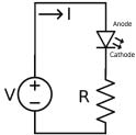
Resistor circuits are simple, take up little space, and are low cost. They limit current by dropping the voltage supplied to the LED. The fixed resistance requires a constant voltage source to deliver a constant current. They waste power through the resistive load, generating excess heat. LEDs may be damaged if the line voltage fluctuates.
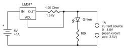
Linear regulators are widely available, inexpensive, and provide current regulation over a wide voltage input. A linear regulator works like a variable resistor in a voltage divider network, constantly adjusting to maintain a predefined output voltage. They use a simple feedback loop to control the voltage applied to the load. They can prevent the load from seeing too much voltage if line voltage fluctuates. However, the greater the difference between the supply voltage and output voltage, the lower the efficiency as the difference is dissipated as heat. Efficiencies of 50% or less are common, meaning this circuit can waste as much power as the LED string is using.
Switch mode power supply (SMPS) allow for wide voltage input ranges, are typically 85% or more efficient, can provide boost (stepup) or buck (step down) voltage control, and have the most options for self-regulation and dimming control. The downside is they can be bulky, cost more, and generate greater EMI/RFI which could disturb adjacent or connected equipment. Because they are more complex, they require greater engineering development effort.
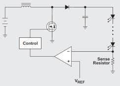
An open loop controller indirectly regulates LED current by switching an inductor on until a preset current limit is reached, at which time the switch turns OFF, the field stored within the inductor reverses, and the stored charge is released into the LEDs. The cycle repeats on the next clock cycle.
A closed loop controller can perform open loop control as above, but has an additional control loop that allows tighter regulation of LED current. The LED current is directly monitored, (as opposed to just the inductor current), and the gating of the switch is in response to LED current and not simply inductor current. This results in a substantial improvement in LED current accuracy and reduced LED ripple current.
Many other protective features may be implemented to protect the line or the light itself using this design, which will be discussed further on.
Power circuits designed to drive high-power LEDs must incorporate active protective features for safe and reliable operation. These can include Soft-Start, Short Circuit Detection, Over Voltage Protection, Under Voltage Lockout, Thermal Rollback, and Cycle-by-Cycle current limiting.
Soft-Start (SS) provides current to the LEDs in a controlled ramp-up from zero to the maximum operating current, as opposed to a step surge from zero to maximum at startup. Soft-start greatly reduces harmful in-rush current at power-up.
Short Circuit Detection (SCD) detects excessive input or output current. Usually, when a short-circuit is detected in an LED string, a try-wai-tretry loop commonly called a “hiccup timer” will initiate a sequence in which the controller will immediately stop when a short circuit is detected, wait a brief period, then restart. If the short circuit persists, the controller can be designed to latch off after some number of re-try’s.
Over Voltage Protection (OVP) – detects an output over-voltage condition, which would occur if a single LED in a series string of multiple LEDs became “open circuit”, and the constant current driver attempts to ramp up voltage trying to maintain a preset current. OVP detects the over-voltage output from the constant current drive to the open circuit, and initiates a try/retry loop with “hiccup timer”, as above. If the over-voltage condition persists, the controller will latch off after some number of re-try’s.
Under Voltage Lockout (UVLO) is utilized to prevent the LED power supply from drawing excessive current at powerup with an undervoltage power supply. This feature is generally implemented as a threshold detector on the input, requiring that the input voltage be at least some minimum voltage before start-up of the switchmode power supply (SMPS). Without this feature, the controller would potentially start at an input voltage lower than expected, drawing excessive current from the input source. It is best implemented as a non-latching feature, allowing the unit to recover when source voltage is increased.
Thermal Rollback (TRB) utilizes a temperature sensor, thermally coupled to the LED engine providing feedback to the controller. When the LED temperature exceeds a pre-defined upper threshold, LED current is gradually decreased in accordance with the temperature sensor, maintaining a safe LED operating temperature. Operating LEDs outside of their safe operating area (SOA) greatly reduces their lifespan and efficacy. Temperature rollback has the advantage of providing useful light even in an overheat condition, a feature appreciated by operators in the deep sea. An alternative is a thermal switch that simply turns the light off if the temperature rises to a certain value. These take up little space and are inexpensive.
Cycle-by-Cycle current limiting is a method by which a switch mode power supply (SMPS) examines its FET switch current on each and every switching cycle. If the maximum switch current is exceeded, the gating pulse to the switching FET is terminated until the next cycle is initiated by the controller’s internal clocking cycle. Cyclebycycle current limiting prevents damaging, instantaneous, over-current from destroying the FET switch or the LEDs.
Highly efficient drive electronics have been developed to accommodate the wide range of power sources available in undersea manned and unmanned vehicle applications. Power inputs of 1032VDC accommodate a wide range of battery voltages. High-voltage AC/DC (180240VAC, 5060Hz), universal input (85265VAC 50/60Hz), isolated flyback and nonisolated buck/boost converters, plus power factor corrected inputs have all been successfully tested. Miniaturization, both for compactness and reduced implodable air volume, are an important design objective. With battery powered systems in particular, high efficiency is critical design objective. DSPL engineers have tested high output power switch mode regulators that deliver precise and constant current to the LED array at efficiencies exceeding 93%.
Dimming
Vehicle designers have come up with many novel ways of dimming the lights on their vehicles. Dimming control interfaces for underwater lighting include isolated and non-isolated control voltage (05vdc, 010VDC), current loop (420mA), PWM, serial communications, TCP/IP communication, phase control, DMX, variable input voltage and toggle. Many of the above schemes can be used to control a commercial off-the-shelf (COTS) phase control dimmer.
AC wall power in the U.S. is 120V, 60 cycle, single phase. The 120VAC refers to the RMS (root mean square) average value of the sinusoidal voltage waveform. The peak voltage is the RMS value multiplied by the square root of 2 (1.414). Peak voltage of 120 VAC (rms) = 120VAC * 1.414 = 170VAC. This will have important consequence shortly.
Some 120VAC linefed LED lights do not use driver circuits or power supplies. They use the simple, low cost series resistor or linear regulator. These present a risk of flicker using simple dimmer techniques. Other lights, such as DeepSea’s Matrix series, contain integrated drivers and power supplies, so even with a varying AC input, the driver provides constant current and performs dimming with zero noticeable flicker. For the light to be dimmable, the driver must be designed to interpret control signals and produce a range of LED current. The added control circuitry may slightly lower driver efficiency and may cost more, but provides the advantage of a flicker free and broader dimming range. This is important to video imaging systems which are more sensitive to phase blanking and black video frames than film or human eyes.
Phase control dimming is used in household wall dimmers, and is built around a very robust electronic switch called a “triac”. These are electrically very noisy as they delay turnon of the output until a certain phase angle is reached, resulting in very large current transients. These current spikes can get out of phase with the line and cause heating of the transmission lines and wasted energy. These line spikes can also degrade video through cross-talk.
Resistive light sources, such as incandescent bulbs, work well with phase control dimmers as they produce their light by heating an element which makes them react slowly to pulsed power. LEDS, however, are electronic devices and react instantaneously to pulsed power. This will make the LED’s appear to flicker under phase control dimming.
A low cost means of driving LEDs from 120VAC mains is using a bridge rectifier through a current limiting resistor to a series string of LED’s. This has the advantage of making the light somewhat compatible with phase control and variable voltage dimming. The drawback to driving and dimming LEDs in this fashion is the LED will not emit light until the voltage rises to the forward voltage (Vf) of the LED string and will turn off when it drops below that string Vf. Thus, the dimmer is only effective over a small range of control, and the light is susceptible to the “60 cycle” flicker most people are familiar with from fluorescent lights.
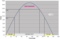
The downside of this approach is LEDs will be overstressed if they are driven at too high a voltage, as happens with an AC supply delivering a peak voltage that exceeds the LED limit. For example, a Cree XPG LED is rated with a Vf of 3.3vdc at 1000ma. Wiring 36 Cree XPG’s in series, the total string Vf would be close to 120V rms. As can be seen in the Fig. 4, the LED string won’t turn on until it gets to Vf(Min) of about 2.64V/LED or 95V in the string. Likewise, the LED turns off at this voltage on the backside of the curve. This means the light is not on for about 35% of the half cycle. The peak voltage would be as high as 170V. The manufacturer calls out the Vf(Max) as 3.75V/LED, or 135V with 36 LEDs in series. The LED is therefore over-driven 40% of the time, which is likely to affect its operational life.
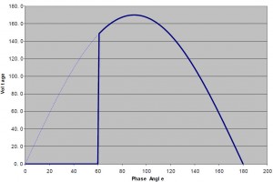
A phase control dimmer delays the application of voltage until a point later in the 0180º cycle. When voltage is applied at some phase angle, say 60º as shown in Fig. 5, electrical power transitions from zero to the corresponding peak value instantly, creating inrush current and EMF signal.
One phase control dimmer we tested dimmed an incandescent bulb from off-to-full bright over a rotational range of approximately 300º out of 360º. We then tried an LED light wired with 36 LEDs in a string as described above. The light went from bright to dim in approximately 30º of the 300º, while the remaining 270º was simply “off”. The designer can provide slightly more dimming range by removing some of the LED’s in the string, thus lowering the overall Vf. However, this will result in higher peak currents through the LED’s which may exceed their maximum recommended values. It will also make the light less efficient as the series resistor will have to drop more voltage, creating more heat.
Another alluring approach to 120VAC light design is the use of the Seoul Semiconductor Acriche, an LED claimed by its manufacturer as “the world’s first semiconductor light source that operates directly from AC power without a converter.” Under the LED silicone lens are two parallel, but reverse polarity, strings of 36 tiny LEDs in series acting as a bridge rectifier. The Acriche requires use of an external current limiting resistor similar to the above “low cost” bridge rectifier design, which drops voltage and lowers system efficiency. While use of Acriche may enable direct compatibility with a phase-control dimmer switch or Variac™, the dimming performance will be at best disappointing with all of the weaknesses of the above low cost bridge rectifier design.
This is not to conclude that LEDs can’t efficiently be dimmed using phase control. DeepSea Power & Light has developed an advanced LED driver compatible with a phase control dimmer switch which provides smooth, continuous LED current with a linear dimming ratio in excess of 400:1 at power outputs over 125W and efficiencies over 85%.
With DC driver circuits, LED brightness is commonly controlled using PWM (Pulse Width Modulation), varying forward current, or both. PWM “chops” the effective “ON” time of the LED string at a rate much higher than can be visibly perceived, altering the average “ON” time of the LEDs, thus varying brightness. Changing the LEDs forward current also affects brightness. Used in combination, very high dimming ratios can be achieved.
Designers incorporating LED lights have several choices in the marketplace to find best fit for space, electrical power, dimming control, as well as optics to focus light in a spot or flood pattern. Interfacing with a larger system requires both the system integrator and the underwater light manufacturer to adopt a common language of design. The designer has many control options at his disposal. Where there is no strict power budget or a need for clean video, the more inefficient, cheaper solutions may be a good fit. Where there is a need for more efficiency or better quality video, the switch mode controller, with its ability to incorporate additional LED protective features, is a good choice.
For further information on LED driver options and design, contact DeepSea Power & Light or visit http://ocean-innovations.net/