

UV IRRADIATION: A New Kind of Antifoulant
By: Chris Bueley, AML Oceanographic
AML Oceanographic has developed a novel UV-based antifouling technology for use on virtually any submerged surface. The performance of the system in reducing fouling induced measurement error on in-situ conductivity cells is comparable to the leading chemical-based system, as demonstrated in a described trial.
Introduction Many systems used to monitor the world’s oceans consist of long-term, in-situ deployments of sensors. It is widely understood that the primary factor limiting the duration of these deployments is biofouling [1], defined as the unwanted and oftentimes rapid accumulation of marine growth on submerged equipment [2]. Unchecked, this marine growth will overwhelm cameras, block lights, confound sensors, and inundate structures. In light of these limitations, significant effort has been exerted over the years towards developing mitigation strategies, with mixed results. Existing commercially available antifouling techniques may be categorized into two groups: (1) mechanical methods that consist of wipers or scrapers, and (2) chemical dosing techniques. Limitations of mechanical antifouling methods include poor reliability and an inability to protect complex geometries; conductivity cells, for example, are difficult to brush effectively. Alternatively, chemical dosing techniques are subject to a range of environmental Concerns.
In previous years, there have been promising investigations into the use of Ultra-Violet radiation (UV) as an antifoulant [1], [3], [4]. This method is attractive as it is non-contact, non-toxic, mechanically simple, and suitable for protection of complex geometries. AML Oceanographic has developed the industry’s first commercially available UV-based antifouling system, which may be used to protect virtually any submerged surface. This article presents the mechanical embodiment of the technology, hereafter referred to as UV•Xchange, and describes a trial that demonstrates that its ability to reduce fouling-induced measurement error is comparable to leading chemical-based techniques.
System Description
UV as an Antifoulant Biofouling
generally occurs in five stages [4], with the first three stages characterized by the progression of organic biofilms, and the remaining two stages described by the growth of higher order organisms. UV primarily functions as an antifoulant by disrupting development of the first three stages.
The driving mechanism of early stage growth is the cellular replication of colonizing cells – a process susceptible to interruption by UV. Much of the radiation present in the UV-C band (200 to 280 nm) is absorbed by DNA nucleotides, which damages them and arrests cellular division. This prevents the replication of early-stage adsorbing cells such as biofilms and other colonizers, precluding progression to late-stage higher order communities and ultimately resulting in the complete arrest of biofouling development.
Mechanical Embodiment
UV•Xchange is designed to provide antifouling protection to any submerged equipment. It is composed of a series of stackable LED modules housed within a glass pressure case, as shown in Figure 1.
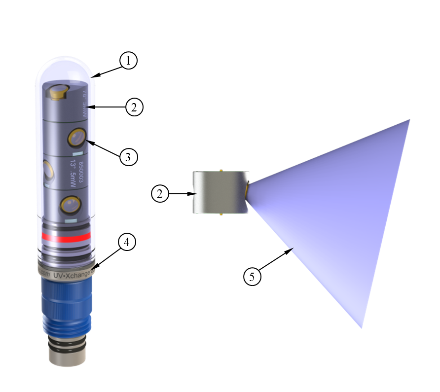
The LED modules (2) emit UV radiation through the wall of the glass pressure case (1) in broad 70° cones (5) to irradiate target surfaces. Each module may be independently rotated to provide coverage in multiple directions. The stem (4) is compatible with AML Oceanographic X-Series instruments. Operation of the system is controlled through a configurable duty cycle which allows users to tailor the level of protection to the aggressiveness of a particular fouling environment.
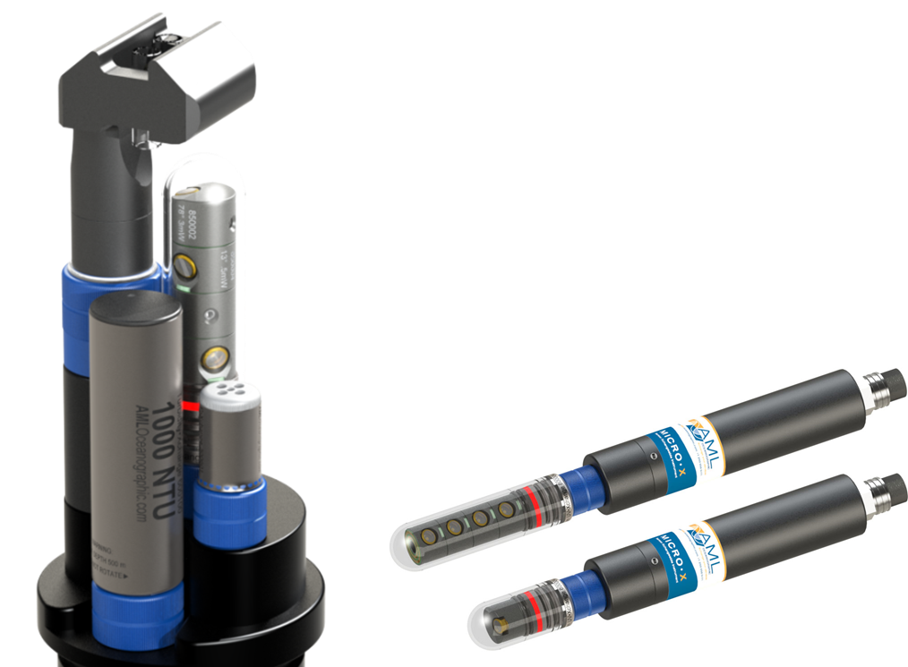
To provide protection to AML sensors, UV•Xchange mounts on an endcap with the LED modules appropriately aimed, as shown in Figure 2. Alternatively, mounting UV•Xchange on a Micro•X allows the system to be fixed to any equipment, enabling the protection of any lights, cameras, sensors, etc.
UV•Xchange In-Situ Trials
HURL Demonstration
AML Oceanographic has conducted a number of in-situ trials to establish the performance of UV•Xchange. One such trial has been conducted at the Hawaiian Undersea Research Laboratory (HURL), located near Honolulu, Hawaii – a location known for its aggressive fouling. The 2- month trial consisted of four Metrec•X instruments outfitted with conductivity sensors. Two of the instruments were protected with UV•Xchange systems (referred to as UV1 and UV3), with two left unprotected as controls. Reference conductivity readings were provided by a Sea-Bird CTD (Sea-Bird Electronics, SBE-19 PlusV2) with a chemicalbased antifouling system.
After 2 months, the housings of all instruments were heavily fouled, as shown in Figure 3. The primary control conductivity sensor (Figure 3, left) was inundated with growth while the sensing elements of two UV-protected instruments (center and right) remained clear.
Of note is the protection provided to the instrument rack from incidental UV radiation, identified as (3) in Figure 3. This demonstrates the broad area of influence of a UV•Xchange module (refer to item 5 in Figure 1). For reference, the distance from the LED module to the clean area is approximately 12 cm in the middle image.
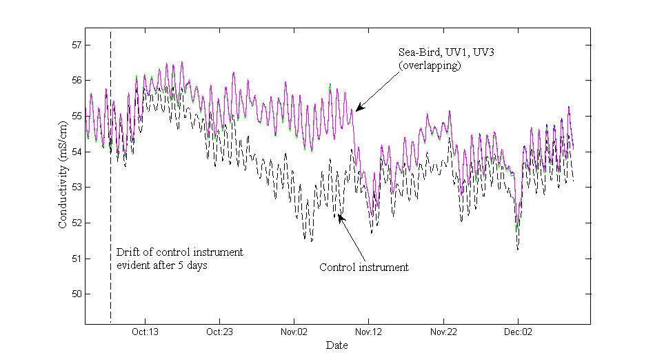
A plot of measurements from each instrument is included in Figure 4. As shown in the figure, the unprotected control instrument (dashed line) exhibits clear deviation from the three protected instruments (Reference, UV1, UV3) in less than one week. In contrast, measurement plots from the protected instruments overlap for the entire duration of the deployment and no systematic drift is evident.
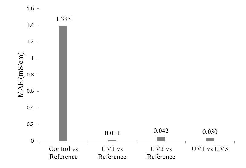
Performance of UV•Xchange may be quantified through comparison of Mean Average Error (MAE), defined as the mean of differences between two data series. The MAE error budget is the maximum error attributable to sensor accuracy limitations and is calculated by summing accuracy specifications of the compared sensors. For example, the MAE for the control sensor versus the reference sensor is 1.395 mS/cm, as shown in Figure 5. This significantly exceeds the error budget of 0.013 mS/cm (based on published accuracies of 0.003 mS/cm and 0.010 mS/cm for the Sea-Bird and AML sensors, respectively) and indicates clear measurement error in the control (unprotected) sensor due to fouling. In contrast, the MAE for UV3 against the reference sensor and UV1 is calculated to be 0.042 and 0.030 mS/cm, respectively – a clear improvement over the control instrument. Measurement disagreement is attributed to sediment buildup on the horizontal conductivity tubes of UV3 (refer Figure 3). Alternatively, the MAE for instrument UV1 against the reference sensor is 0.011 mS/cm. This is less than the error budget and indicates that UV•Xchange’s ability to limit foulinginduced measurement error is comparable to chemical-based methods. In summary, the HURL trial has quantifiably validated the ability of UV•Xchange to retard biofouling on in-situ sensors and structures.
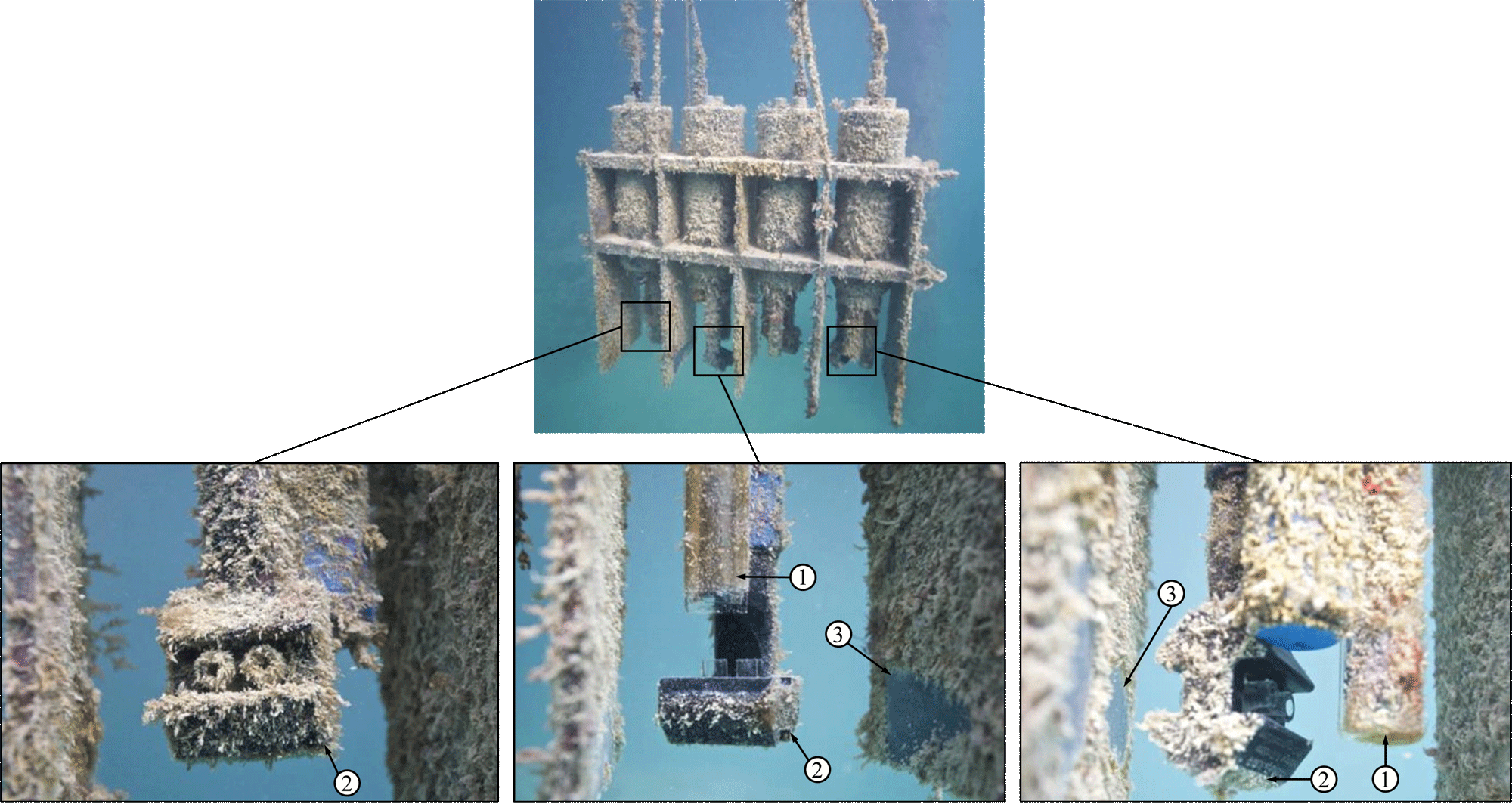
Figure 3: AML instruments after 2 month deployment at HURL. (1) UV•Xchange, (2) conductivity sensors, (3) incidental clean patches on rack. From left to right: primary control sensor, UV1, UV3.
Ocean Networks Canada Demonstration
In addition to the trial conducted at HURL (and others not mentioned), AML Oceanographic has partnered with Ocean Networks Canada (ONC) to conduct a technology demonstration of UV•Xchange in a long-term in-situ deployment. In October of 2013, AML Oceanographic deployed three instruments to the Folger Pinnacle observatory off the coast of Bamfield, British Columbia. Two instruments are protected by UV•Xchange systems and one is an unprotected control. The trial is currently ongoing and is scheduled to operate for a year, with high-definition video feedback of the instruments and real-time measurements available to the public (refer to http://www.AMLoceanographic.com).
Figure 6 includes an image capture from the observatory’s camera after 2 months. As shown, growth on the control instrument (far right) is extensive while the two UV•Xchange protected sensors (left and center) remain free of fouling. Final results from this technology demonstration will be published in late 2014.
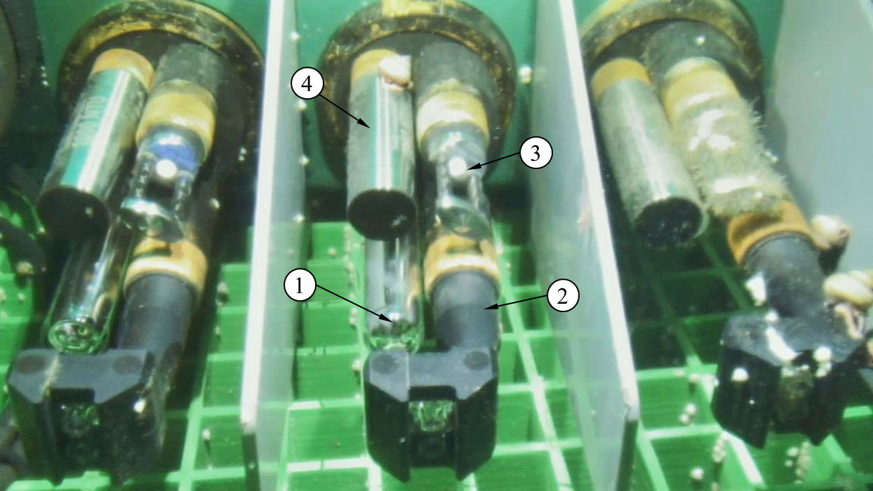
Figure 6: AML Oceanographic instruments deployed on ONC’s Folger Pinnacle platform, approximately 2 months after deployment. Left and center instrument protected by UV•Xchange system, right instrument is unprotected control. (1) UV•Xchange system, (2) C•Xchange sensor, (3) SV•Xchange sensor, (4) Tu•Xchange sensor. Extensive barnacle and algae growth is apparent on the unprotected conductivity and sound velocity sensors, respectively.
Conclusion
UV is an attractive antifoulant as it is non-contact, mechanically simple and may be used to protect complex three-dimensional surfaces. AML Oceanographic has developed an antifouling system capable of protecting virtually any submerged surface. The efficacy of UV•Xchange has been established through a number of successful in-situ trials and performance has been shown to be comparable to existing chemical-based systems. Due to the inherent advantages of this system over existing commercially available technologies, UV•Xchange may allow for deployments and durations not previously possible. Further information about this system is available at www.AMLoceanographic.com.
Remarks
The author of this article extends thanks to Ocean Networks Canada and the Hawaiian Undersea Research Laboratory fortheir support in testing this technology.
References
[1] K. E. Cooksey and B. Wigglesworth-Cooksey, “Adhesion of bacteria and diatoms to surfaces in the sea: a review,” Aquatic Microbial Ecology, vol. 9, no. 1, pp. 87–96, 1995.
[2] J. S. Patil, H. Kimoto, T. Kimoto, and T. Saino, “Ultraviolet radiation (UV-C): a potential tool for the control of biofouling on marine optical instruments,”Biofouling, vol. 23, no. 4, pp. 215–230, Jan. 2007.
[3] A. Lakretz, E. Ron, and H. Mamane, “Biofouling control in water by various UVC wavelengths and doses,” Biofouling, vol. 26, no. 3, pp. 257–267, Apr. 2010.
[4] L. Delauney, C. Compere, and M. Lehaitre, “Biofouling protection for marine environmental sensors,” Ocean Science, vol. 6, no. 2, pp. 503–511, 2010.
[5] “UV Disinfection Guidance Manual.” Environment Protection Agency, Jun-2003.